OPTICAL COUPLINGS
Datasheet Optical Coupling
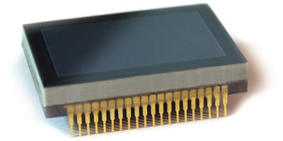
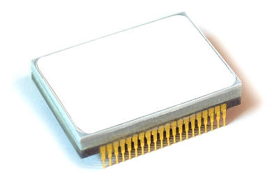
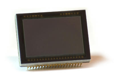
As a manufacturer of imaging equipment for thin sections BEWTEC has profound experiences in proximity optics and opto-mechanical couplings. Optical sensors (CCD or CMOS) can be coupled to any optical elements either directly (proximity coupling) making use of fiberoptic image guides or with classical lens or relay optics. Fiberoptic image guides outperform the light transmission of any classical relay optics (lens optics) by far when a Lambertian distribution is to be imaged, e.g. 70 % transmission for luminescent materials used for signal conversion to the visible spectrum (magnification 1).
Applications:
customized applications, scientific instruments and OEM components
- Special Detectors
- Electron microscopy (REM, TEM)
- X-ray imaging
- X-ray microtomography
- Multi-Channel-Plate Detector Systems (Open MCP Detector)
- VUV‑ and EUV-detectors and EUV-microscopy
- Imaging
- Low-light imaging with or without image intensification due to excellent light transmission
- Ultra-fast imaging with gated image intensifier
- Mechanics
- Adaptation of apertures with magnifying or minifying tapered fiberoptics, magnification 1 : 1 up to about 1 : 5
- Displacement of the focal plane without relay optics
- Protection against ambient influences
Characteristics:
- Outstanding 70 % total transmission for proximity optics (1:1 imaging ratio) hits transmission for lens optics
- What kind of sensors? – Coupling of 0‑, 1‑ and 2-dimensional sensors possible, like
- Photodiode Arrays
- PIN-Diodes
- CCDs
- CMOS
- line-CCDs
- What kind of fiberoptics?
- Coupling of Fiberoptic Plates, specially grinded Fiberoptic Windows or Fiberoptical tapers possible (FOP, FOW, FOT)
- A wide range of mechanical dimensions possible
- fiber diameter 3–4µm, 5µm, 6µm, 10µm or more
- tapers: imaging ratio about 1 : 1 up to 1 : 5 with magnifiying or minifiying tapers
- Fiberoptic surfaces can support thin films or layers of optically active materials, e.g.
- deposited layers of luminophors (e.g. phosphors like Gadoliniumoxisulfid, P43)
- deposited thin transparent films like the electrical conductive ITO
- covered with plates of many optically active materials like EOM, AOM
- scintillator materials like CsI
- YAG-crystals etc.
- thick Fiberoptic Plates provide additional protection of the open sensor against dust, mechanical impact, chemicals, vacuum or radiation (heat, electron bombardement, x-rays and radioactive irradiation).
- Manufacturing of replacement units possible:Enhanced ex‑ and inter-changability of a fiberoptically coupled sensor to other optical devices like image intensifiers or other special instruments
- Adaptation of refractive index possible
Database:
Here are some examples of various sensor types to be extended with fiberoptic elements according to customers‘ demands (list based on our positive experiences).
-
Sony
- Sony ICX 083AL
- Sony ICX 259AL (1⁄3″)
- Sony ICX 259AK (1⁄3″)
- Sony ICX 285AL
- Sony ICX414AL
- Sony ICX 419AL (1⁄2″)
- Sony ICX 418AL (1⁄2″)
- Sony ICX423AL
- Sony ICX429AL
-
E2V/Atmel/Thomson
- TH7888
- TH7899
- line CCDs (Atmel)
-
Kodak
- KAF1602 LE
- KAF 1603ME
- KAF-1001E(S9NE6739)
- KAI 11000M
- KAI 11002
-
Dalsa
- Dalsa FT01104203XMY0611010
-
Sharp (1⁄3″)
- Sharp RJ 2361
-
Different large CMOS
- (E2V, Atmel, Thomson, Fill Factory)
the following older material is reported to work, too:
DALSA IA-D1–0064E, IA-D1–00124E, IA-D1–0256D, IL-C6–2048B
EEV CCD15–11–5–656
Fairchild FCCD 181 IEDC
Kodak C2L, KFA 1000, MA 361
Philips FT 1010, FT-18V1
Reticon RL 0128 KAU-011, HS0256JAU-11, RA 1024 JAU 022, RL 2048 SAQ-011
Sony ICX 022, ICX 024, ICX 038, ICX 039, ICX 055, ICX 083, ICX 085
Thomson TH 7696, TH 7863, TH 7883, TH 7888, TH 7895, TH 7896.
Practical:
Please note that a protective window of the CCD is to be removed in order to bring the active area of the sensor and the fiberoptic apertures into close proximity.
A variety of procedures are at hand to remove the protective windows of different CCD types. However, if possible, the CCDs should be procured from the manufacturer with temporary windows instead.
Removing of the protective window of the CCD bares an average risk of 10–20 % to damage the CCD, depending on the CCD. CCDs supplied with non-permanent protection windows will reduce the risk of damage to about 5 % for regular operations or modification.
Please note: In the case of damages to the unit we assume liability only at rough negligence.


